
To tree, or not to tree…

Trees, plants, grass, really any kind of organic vegitation can be challenging to replicate in 3D, and often come with the caveat of high polycounts - which can put a strain on even the beefiest computer system.
If you think about a tree and its structure - trunk, limbs, branches, twigs and leaves, it’s easy to see how the polycount can run into the millions. Did you know that a mature healthy tree can have a leaf count in the region of 200,000 leaves!*
So why would we bother to make our own tree models when it seems like a challenging process and there are plenty of freely available models to download online. The answer is two-fold, firstly, control. By modelling from scratch we are able to have more control over the finer details of the model - it’s shape, spread, branch count, textures and most importantly polycount. Secondly, its fun and you can learn a lot, not just about the modelling process but also about the environment that surrounds you.
The following article explains my process for creating tree models from scratch; we’ll explore topics such as tree identification, photogrammetry techniques, blender plugins for mesh generation and texture capture and creation.
*Depending on species and age.
Software
Firstly I thought it would be beneficial to share what software I use to help me create my tree models. Whilst some require a paid subscription others do not and there are often free to use alternatives to the paid ones. Techniques may differ from software to software however the principles still remain the same.

3D Studio Max
Corona Renderer
Blender
Meshroom
Photoshop CC
Tree Identification
Before any modelling can take place we need to gather some reference images. References are crucial for understanding the shape and form of what we are trying to model.
Each species of tree will have its own unique characteristics which we need to try to reflect in our models. For example the conical shape of a Norway Spruce is much different to the domed shape of an English Oak.
Google is a good place to start, however, I would recommend getting out and exploring on foot, taking pictures and collecting leaf samples of what happens to be growing in your local area. This way you are able to create a repository of references - from overall shots of entire trees to detailed images of their leaves and other structures.
If you’re like me then you can only point out a handful of tree species by looking at their leaves or bark. So if you’re struggling to differenciate between your Alders, Elms and Oaks then look no further than the PlantNet app. PlantNet is super easy to use and allows you to identify all sorts of fauna by simply photographing them with your smart phone. It’s also a great citizen science tool, helping to identify and catalogue species of plants native to your area.

Great Maple Leaf

Common Oak Leaf

Common Birch Leaf
Mesh Generation
Once we’ve collected our references and decided on a species of tree to try to replicate, we can make a start on mesh generation.
If you’ve ever looked closely at a tree’s composition you’ll understand that they are incredibly complex, detailed and diverse structures. It’s unreasonable, therefore, to take on the challenge of modelling a tree from the primitives contained within your 3D application of choice, it will take hours!
We need a procedural technique that can quickly iterate the shapes and forms found within a trees structure so we can efficiently create a range of different tree models in minutes. The Modular Tree addon, for Blender, is the tool we need to accomplish this task.
Modular Tree is an excellent free addon developed by Maxime Herpin, it uses a node based system that allows us to quickly generate and modify a trees structure by adjusting a series of parameters contained within each node. We can specify how tall we want our tree to be, how many branches it has, how gravity affects those branches, the split angle of the branches, the shape and size of the trees leaves…the possibilites are truly endless. There are also a few preset examples which can be loaded in and modified.
By using our reference images in cobination with the Modular Tree addon we can easily generate a realistic tree mesh in minutes, ready for the next step of the process.
Photogrammetry
To add an extra bit of realism to my trees I like to combine the basic tree mesh with some photogrammetry. This is a great way to add some extra variety to your trees and, because the photogrammetry models are generated from real world photography, it amps up the realism and really helps to sell the final image.
Photogrammetry is the technique of using photographs to work out measurements between objects - by taking a series of photographs all the way around an object we can reconstruct it in 3D using these measurements.
AliceVision’s Meshroom is a brilliant piece of free software that is able to automate this process and generate fantastically detailed meshes, ready for us to use in our 3D applications.
Photogrammetry Photography - Best Practice
There are a few guidelines we must follow, to get the best results, when taking photos for use in photogrammetry.
Lighting Conditions -
When photographing an object for photogrammetry it’s best to ensure the object is evenly lit with diffuse light. No sharp shadows, no partially lit objects - we must keep a consistant lighting setup throughout. This is because the lighting information contained within our photos will be baked into the generated texture maps of the object. If we have any shadowed areas on our object these will show up in the texture map - not ideal when it comes to lighting the object in our chosen 3D application. We want to be able to dictate which areas are in shadow and which areas are not. This diffuse lighting setup is easy enough to do in a studio environment, but what if we are shooting outside?
To recreate a diffuse lighting setup outside it’s recommended to shoot on a cloudy overcast day. The clouds will act as a giant softbox for the sun helping to diffuse the light and create an even lighting situation, ideal for photogrammetry.
Camera Setup -
While its perfectly acceptible to use a smartphone camera to take your photos, I would recommend using a DSLR camera combined with a tripod. Shoot in manual mode so you have control over the f-stop, ISO and exposure settings. We want every photo that we take to have consistant lighting values and to be in sharp focus. I typically set the ISO to 100 and use the exposure meter to determine what my f-stop should be.
A tripod coupled with a 2sec delay on the shutter will help ensure the images we are taking are sharp and in focus, eliminating any micro movements that could blur the image - blurry images are a big issue and you will find Meshroom will discount any images it determines to be too blurred.
Photographs -
Generating a comprehensive set of photographs is crucial for photogrammetry modelling. A full 360° around the object needs to be captured, from various elevations and distances in order to generate the necessary information needed to reconstruct the object in 3D.
An overlap of at least 60% between photos is recommended and will produce better results when the mesh is generated. Detail shots can be combined with overall shots to maximise the data input.
Photogrammetry Mesh Optimisation
Once we have our mesh generated in Meshroom we need to clean it up and optimize it for use within our 3D application of choice. I use 3D Studio Max to complete this step, but the principles remain the same regardless of which software you’re using.
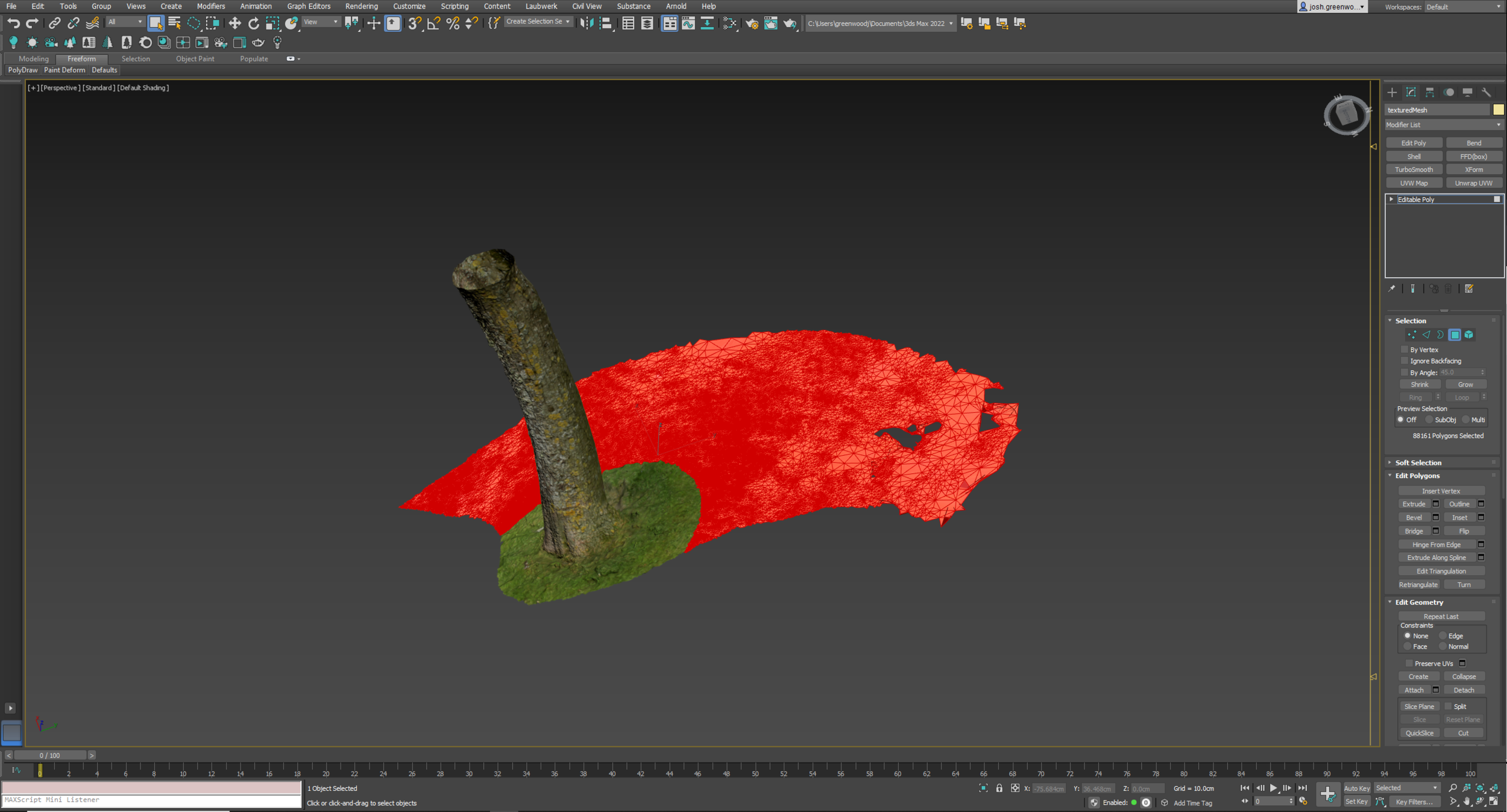
As we can see from the screenshot below, the 3D mesh generated in Meshroom contains not only our tree trunk but also some of the scenery surrounding it. Our aim here is to clean up the mesh leaving only our isolated tree trunk.

To do this we need to import the “texturedMesh.obj”, found in the Texturing folder of the MeshroomCache, into 3D Studio Max.
You may notice that it imports the mesh in a strange orientation, it’s crucial that you do not move the model from this position, as, when it comes to re-baking the textures, Meshroom will not know how to project them onto the model.
From here we can select the faces we wish to remove using the lasso selection tool and hit delete.
Once we have our cleaned up mesh the next step is to optimise its polycount. By hitting 7 on the keyboard we can see that this particular model has a polycount of just over a million…this needs to be reduced significantly.
We can do this by adding a ProOptimizer to our modifier stack. Hit calculate and wait for it to crunch the numbers, this could take a few minutes depending on your machine. Once the vertex count has been calculated we can reduce it to around 20% of its original total, this gives us a good balance between optimisation and preservation of detail. Convert the optimised mesh back to an Editable Poly.
As you can see in the screenshot below we have managed to retain a decent amount of detail while at the same time reducing the polycount to a more manageable number.
All that’s left to do now is unwrap the UV’s and flatten them so we have one texture file to work with.
Add an unwrap UVW modifier to the stack of our optimised mesh and open the UV editor.
In the UV editor we need to open the Mapping tab and select “Flatten Mapping” hit OK on the dialog box that pops up and wait for 3D Studio Max to do its thing. The resulting map isn’t the most elegant of UV maps but is absolutely fine for the purposes we are using it for.
We can now export the mesh as a new .obj file. Remember where you save it as we need to reference the location when we import it back into Meshroom.
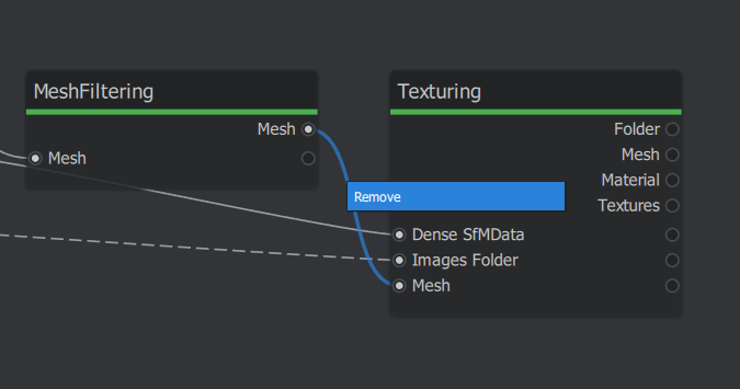
Once back in Meshroom unlink the MeshFiltering node from the Texturing node. You will notice the generated mesh will disappear from the viewport.
Click on the Texturing node - in the dialog box to the right you will notice that the “Mesh” parameter will be blank. This is where we need to reference our optimized mesh we created in 3D Studio Max.
Locate the .obj file in windows explorer, click and drag it onto the empty Mesh dialog box.
Hit the start button at the top of the screen and you will see Meshroom resume the mesh generation using our imported mesh.
We now have a clean, optimised mesh complete with textures!
By repeating this process for a number of different tree trunks we can start to build up a nice library of models to use in future projects.
Photogrammetry Mesh Blending
Now that we have our optimised photogrammetry tree trunk model we can start to combine it with the base tree mesh we created in Blender. I do all the following in 3D Studio Max.
I start by deleting the polygons that form the base of the tree trunk of our Blender mesh and then import the photogrammetry obj file into 3D Studio Max and move it into position at the base of the tree, ensuring there is a slight overlap between both meshes.
From here I use the soft selection tool to blend the two meshes together and create a seamless join.
Textures/Materials
Now that we have a finalised model we can start to add it’s textures. We’ll be using the PBR shading method to do this.
The PBR (Physically Based Rendering) shading method is fundimental to creating realistic and believable materials. It works by using a combination of specific texture maps to describe the surface of a material. These include, but are not limited to, Diffuse, Roughness, Translucency, Opacity, Normal & Displacement.
By using the reference images we collected at the beginning of this whole process we can start to generate our own PBR texture maps for use with our tree model.
Leaves
To create the leaf materials for our tree we need to generate the following texture maps - Diffuse, Translucency, Roughness, Opacity & Normal.
Diffuse -
For the diffuse texture I create a 1024x1024 blank document in Photoshop and add one of my leaf references.
Using the magic wand selection tool I select areas of the leaf until I have a perfect selection of the entire leaf, I then delete the background leaving just the leaf cut-out visible.
By Ctrl left clicking on the leaf layer in the layer explorer I’m able to select the entire leaf cut-out, I then navigate to Select > Modify > Contract and contract the selection by 3 pixels. I then invert the selection and use the Content Aware Fill to fill in the blank background with leaf data. This will ensure that their will be no “haloing” present around our Diffuse texture once combined with the Opacity map.
Translucency -
The Translucency map controls how translucent the material will be and how that translucency is represented at render time.
If you look at a leaf of a sunny day you will notice that when sunlight hits the leafs surface some of its energy passes through to the other side of the leaf, creating a sort of subsurface scattering effect, illuminating that side of the leaf.
To replicate this in our material we can use the Diffuse map we’ve already created and raise its brightness intensity to mimic this illuminating effect. We can then adjust the translucency strength parameter in our materal to dictate how strong this effect will be at render time.

Roughness -
The Roughness map controls how reflective our material will be. It works by translating black and white values into reflectivity values. The lighter areas of the texture map will have higher reflectivity and the darker areas will produce a “rougher” or less reflective surface.
In order to create our Roughness map we need to remove the colour values of our Diffuse map and turn it into a black and white image. We can do this in Photoshop by adding a black and white filter to our layer stack and then adding a curves adjustment layer on top of this, giving us control over the black and white values.
Leaves tend to have a slight bit of reflectivity depending on the species of tree, so our aim here is to create a semi-rough texture - which would translate to a grey midtone type of image.

Opacity -
The Opacity map controls which parts of our object are visible and which parts are hidden.
Typically when creating a tree model the leaf geometry is made up of single square planes dupilacted thousands of times across the model. In order to show these regimented square planes as complex leaf shapes we need to effectively cut-out the leaf shape by hiding the surrounding geometry.
In an Opacity map black areas control which parts of the texture are hidden while the white parts control which areas are visible. In our material we want the leaf shape to be visible and the rest of the 1024x1024 image to be hidden, so the leaf we will show as pure white and its surrounding background will be pure black.

Normal -
Normal maps control elevation data and are able to fake the lighting of bumps and dents across a material. They are used to add fine detail to an object without the need for adding extra geometry (polygons).
In Photoshop CC its actually very simple to generate these kinds of maps, all we have to do is navigate to Filter > 3D > Normal map and a normal map of whatever layer you have selected will be generated. There are control parameters inside the pop up dialog box that allow you to fine tune the normal map to show as much or as little elevation detail as you like.
As you can see from the example below, I have used our Diffuse texture and generated the normal map straight from this, allowing the fine vein structure of our leaf to come through.

Bark
A tree’s bark texture can vary massively depending on the species of tree. From the smooth appearance of beech bark the the gnarley and fissured texture of Scots Pine bark.
We can use the same PBR fundimentals for the bark as we did for the leaf materials. Using our reference images we can create seamless bark textures to tile across our tree model.
For bark I like to create a slightly higher resolution texture than I did for the leafs. 2048x2048 or 4096x4096 will usually work pretty well.
In Photoshop I create a 2048x2048 blank document and then open a few different bark reference images (all from the same species of tree). I select the areas of bark I wish to use and copy them to the master document, laying them out so they completely cover the space.
Using the clone stamp tool I make sure any visible seams are covered up so the texture appears as one image. I then offset the image by 1024x1024 pixels so I can repeat the same process on the visible edge seams and create a fully tileable image.
I then repeat the steps outlined above to create all the maps needed for the bark material which typically will be - Diffuse, Roughness & Normal. If the bark is particularly gnarley I may also create a Displacement map to boost the amplitude of the cracks and fissures.

Downloadable Assets
Well done for making it this far! Hopefully the information I’ve outlined above will help you to make a start creating your own tree models.
As a thank you for taking the time to read through the article, I’ve included a link below which will take you to my SketchFab page where you can download some of my photogrammetry tree trunk assets.